| RETURN | History |
Pulse Code Modulation
PCM is a Time-Domain Waveform coding method and is defined within CCITT G.711, and AT&T 43801. Basically, an analog signal is sampled at a rate of 8000 times per second. In each sample, the amplitude of the signal is assigned (quantized) a digital value.
For a true linear system, the value of each “step” is uniform, requiring anywhere from 11 to 14 bits to transmit. However, PCM, as defined and standardized, utilizes a logarithmic scale in the weighting of each step.
There are two PCM algorithms defined within CCITT G.711, called “A-Law” and “Mu-Law”. Mu-Law PCM is used in North America and Japan, and A-Law used in most other countries. In both A-Law and Mu-Law PCM, the values used to represent the amplitude is a number between 0 and +/- 127; therefore, 8 bits are required to represent each sample (2 to the eigth power = 256).
It can be seen then that PCM operates at a rate of: 8 bits/sample * 8000 samples/sec = 64000 (64K) Bits Per Second.
PCM Numerical Value Representation
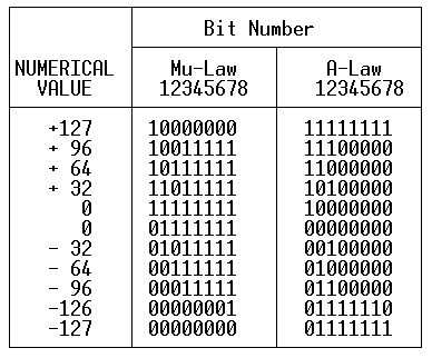
The following table indicates the bit/byte patterns transmitted for particular numerical values:

The left-most bit (Bit 1) is transmitted first, and is the Most Significant Bit (MSB). This bit is known as the “sign” bit, and is a 1 for positive values and a 0 for negative values (both PCM types). Bits 2 through 8 are inverted between A-Law PCM and Mu-Law PCM.
In A-Law, the even bits (2,4,6,8) are inverted. Thus, an A-Law code of 00000000 is actually transmitted as 01010101 (hexadecimal “55”). In Mu-Law, a zero-level hex value of “7F” is used to represent unequipped DS0 timeslots.
In Mu-Law, the digital sequence of “00000010” is substituted for the -126 and -127 numerical values (“00000001” and “00000000”, respectively). This process is known as B7ZCS (Bit 7 Zero Code Suppression) or sometimes referred to as ZCS (Zero Code Suppression).
Mu-Law Companding
The Mu-Law compander operates on a logarithmic curve.
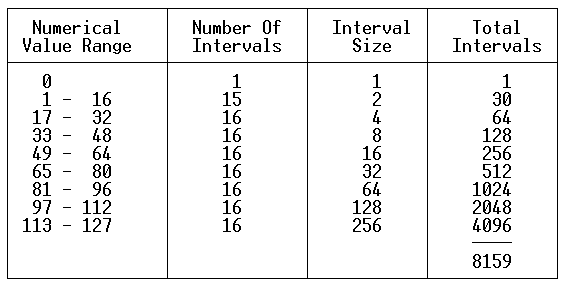
The analog signal is comprised of +/- 8159 equal-amplitude intervals. At the minimal positive power level (11111111), the number of intervals is one, with an interval size of one. Between the numerical values of 1 and 16, there are 15 intervals, each representing two intervals. Reference the following table:

The maximum level (Tmax) supported with Mu-Law PCM is +3.17 dBM0.
A-Law Companding
The A-Law compander operates on a logarithmic curve.
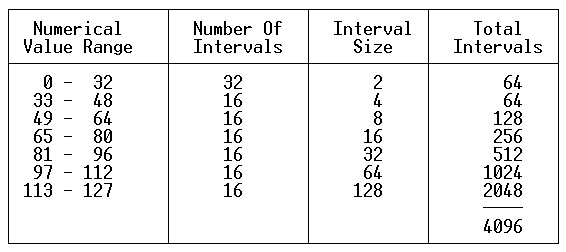
The analog signal is comprised of +/- 4096 equal-amplitude intervals. Between the numerical values of 0 and 32, there are 32 intervals, each representing two intervals. Reference the following table:

The maximum level (Tmax) supported with A-Law PCM is +3.14 dBM0.
A-Law — Mu-Law Comparisons
Note that by reducing the A-Law interval size in half (doubling the number of intervals to 8192), a fairly accurate comparison of the two quantizing algorithms can be achieved.
At all numerical values between 33 and 127, the two algorithms perform similarly. However, the added granularity of the Mu-Law steps below numerical values of 32 results in slightly improved Signal-To-Quantizing Distortion ratios at low levels. The Mu-law has slightly higher quantizing noise since the all-zero word is not used.
At the application level, there is no noticeable difference in voice performance between these two algorithms!
Test Tone Patterns
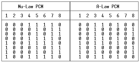
The following table contains bit/byte sequences that when transmitted, will generate a 1000 Hz tone at 0 dBM0. This tone is known as a digital milliwatt. As mentioned earlier, the MSB, Bit 1 is transmitted first.
Note that the bit pattern for Mu-Law PCM is such that bit two is a zero for all eight bytes. IF THIS PATTERN IS SENT ON ALL DS0s OF A D4 CHANNEL BANK SYSTEM, THE ATTACHED EQUIPMENT/FACILITY WILL REGISTER A YELLOW ALARM CONDITION (Bit 2 = 0 for all DS0s in a frame)!
