| RETURN | DDS Overview |
DDS DS0 Byte Formats
Introduction
The real intricacies of DDS lie in how DDS channels are transported in standard 64K DS0s through the digital networks. This document describes typical methods for implementing DS0 DDS transport. Discussed herein are T1 implementation concerns, and also the actual DDS byte structures for DS0 transport of Subrate and Standard-rate DDS channels, including secondary channel operation.
The T1 Multiplexer
Long distance DDS transport is usually provided by T1DM multiplexers within the Central Offices. The T1DM (T1 Data Multiplexer) is capable of carrying up to 23 DS0s. Framing is usually of the standard D4 type, however, DS0 number 24 is used for fast synchronization. The breakdown of DS0 #24 is as follows:
      <---    1 0 1 1 1 Y R 0           Y = yellow alarm
                                        R = 8 KBPS Remote channel
The reframe time when using DS0 #24 in this manner is around 1.125 mS, versus approximately 50 mS for regular D4 synchronization. This helps to achieve the high availability objective of DDS.
Additionally, the yellow alarm indication is propagated in the DS0 24 timeslot. In DDS transport, some control codes and data codes within a DS0 may contain bytes with bit 2 set to zero. This could cause unnecessary yellow alarm generation in standard D4 framing, especially since some data codes and control codes [e.g. Mux OOS code – hex 1A] may have bit 2 equal to a zero. This phenomenon will not occur with T1DM systems.
The T1WB4 and T1WB5 multiplexers are also used to transport DDS data. These multiplexers permit more efficient use of the T1 line by facilitating transport of both voice and data. Each of these multiplexers can support two T1 lines, allowing for tandem interconnection.
The T1WB4 can support up to 12 data DS0 channels, with the remaining 12 DS0s used for voice. The T1WB4 is now obsolete.
The T1WB5 can support up to 24 data DS0 channels, if necessary.
Both the T1WB4 and T1WB5 can generate a T1 frame that is compatible with the T1DM, by installing an additional circuit pack.
D4 Channel Banks may optionally be equipped with “Dataport” capability. Equipped with Dataport, all D4 Channel Bank systems may be considered as potential candidates for DDS transport.
Although the majority of T1 systems meet the error performance criteria necessary for DDS, line selection based upon error rate tends to impose problems regarding what End Offices can be served with DDS. As a result, Dataport facilities may be equipped with Forward Error Correction (FEC) schemes.
For sub-rate DDS (2.4, 4.8, 9.6 KBPS), error correction is based upon a majority voting scheme. A transmitted DS0A byte is repeated at least five times. The receive circuitry will compare each bit within each of the five bytes. If three out of five bits are the same, the state of the bit is considered valid. For random error distribution, a T1 error rate of 10 E-3 can result in a dataport error rate of 10 E-8 (or better) when this scheme is employed.
For 56 KBPS rates, a Bose-Chaudhuri-Hocquenghem (BCH) Error Correction scheme is used. This requires that an additional DS0 be used to transport the BCH parity byte. The structure of the BCH code used ensures that any single or double bit error occurring in the 16 bits (data + parity) will be corrected. About 1/3 of those cases in which three bit errors occurred can be corrected.
The Subrate Data Multiplexer (SRDM)
The SRDM takes sub-rate DDS channels (9.6, 4.8, 2.4 KBPS) and multiplexes them into a single DS0. This DS0 is known as a DS0B. An easy way to remember this is to view the “B” in DS0B as meaning a “Bundle”.
The SRDM can typically operate in one of three modes:
          5-channel  : This multiplexes 5 channels (each channel may be 9.6,
                       4.8, or 2.4 KBPS) into a single 64 KBPS DS0B.

         10-channel  : This multiplexes 10 channels (each channel may be 4.8
                       or 2.4 KBPS) into a single 64 KBPS DS0B.

         20-channel  : This multiplexes 20 channels (of 2.4 KBPS) into a
                       single 64 KBPS DS0B.
The Office Channel Unit
The Office Channel Unit is installed in the End Offices and provides the local loop interface to the customer’s premise.
- The OCU provides the “sealing current” to the local loop.
- The OCU provides clock recovery from the received line signal.
- The OCU will output BPRZ signals, clocked from the End Office’s clock source, to the customers.
- The OCU detects and converts control bytes. Network control bytes are converted to line control bytes and vice versa.
- For Subrate DS0A operation, the OCU will normally perform the “byte- stuffing” function. For a 9.6 KBPS channel, a byte is normally repeated 5 times in order to fill the entire 64 KBPS DS0. For a 4.8 KBPS channel, a byte is repeated 10 times. And, for a 2.4 KBPS channel, a byte is repeated 20 times.
- When DS0A operation is used, the DS0 transports only a single sub- rate channel.
- The OCU will also respond to loopback codes.
- The OCU will respond to an alternating OCU loopback code by establishing a loopback towards the network.
- Upon detection of the Channel Loop (CSU) code, the OCU normally responds by reversing the sealing current polarity of the local loop. The CSU at the customer’s premise will detect this and initiate a loop towards the network.
- The OCU may optionally respond to “Latching Loopback” codes.
DDS Standard Rate DS0 Byte Formats
This section describes the DS0 byte formats for DDS channels operating at their primary rates (no secondary channel).
56 KBPS Service
The 8-bit byte present in the DS0 will have the following format:
      | Bit 8 | Bit 7 | Bit 6 | Bit 5 | Bit 4 | Bit 3 | Bit 2 | Bit 1 |
      |-------|-------|-------|-------|-------|-------|-------|-------|
      |   C   |   D   |   D   |   D   |   D   |   D   |   D   |   D   |

          D = Data bit
          C = Control / Data  (1 = data byte, 0 = control byte)
Observe that Bit 8 (“C-bit”) is always a “1” when in “data mode”. This ensures compliance with ones density and consecutive zeroes T1 span requirements. When Bit 8 is a “0”, bits 1-7 represent a network control code. Network control codes are such that ones density and consecutive zeroes requirements are met.
Note that a 64 KBPS DS0 channel is scanned at a rate of 8000 times per second. This means that each bit in the byte represents 8 KBPS. Since Bit 8 is used by the network, the remaining data rate is limited to: 64 KBPS minus 8 KBPS = 56 KBPS.
Subrate Service
For Subrate services (DS0A or DS0B), the 8-bit byte present in the DS0 will have the following format:
      | Bit 8 | Bit 7 | Bit 6 | Bit 5 | Bit 4 | Bit 3 | Bit 2 | Bit 1 |
      |-------|-------|-------|-------|-------|-------|-------|-------|
      |   C   |   D   |   D   |   D   |   D   |   D   |   D   |   F   |

          D = Data bit
          C = Control / Data  (1 = data byte, 0 = control byte)
          F = Subrate framing bit
The “C-bit” is used to indicate whether bits 2-7 represent actual data or a network control code for the Subrate channel.
Observe that since two bits are used by the network, the available data rate is: 64 KBPS minus (2 times 8 KBPS) = 48 KBPS. (5 X 9.6, 10 X 4.8, or 20 X 2.4)!
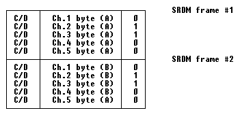
For mixed-rate subrate bundles, bytes from lower speed channels are “stuffed”. For example, the following illustrates the DS0 bytes present for a 5-channel DS0B, with channels 1-4 operating at 9600 BPS and channel 5 operating at 4800 BPS:

DDS Secondary Rate DS0 Byte Formats
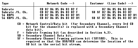
This section describes the DS0 byte formats for DDS channels operating at the secondary rates. The chart below indicates the format of the DS0 bytes and the line code present for both Primary and Secondary Channel DDS formats:

56 KBPS Secondary Channel Service
For 56 KBPS service, the local loop line rate is 72 KBPS. This is determined by:
          56 KBPS / 7 = 8000 BPS  (this is the rate represented by each bit).
          8000 BPS * 9 (9 bit local loop code) = 72 KBPS.
The Secondary Channel Rate is 2.666 KBPS as determined by:
8000 BPS / 3 (every third CD bit) = 2.666 KBPS.
When this type of operation is deployed, the T1 span used to transport this service should utilize B8ZS or any other suitable zero suppression scheme. This is a requirement since there is a possibility that both the Primary and Secondary channel bits may be all zeroes, thus resulting in an all zero DS0 byte.
Subrate Secondary Channel Service
Subrate Secondary Channel Service
For Subrate services, the local loop rate is 12.8 KBPS for 9600 BPS, 6.4 KBPS for 4800 BPS, and 3.2 KBPS for 2400 BPS services. Using 4800 BPS service as an example:
          4800 / 6 (primary line code) = 800 BPS (rate value of each bit).
           800 * 8 (8 bit Secondary Channel code) = 6.4 KBPS.
The Secondary Channel rates are indicated below:
          9.6 KBPS  = 533.33 BPS
          4.8 KBPS  = 266.66 BPS
          2.4 KBPS  = 133.33 BPS
Using 9600 BPS service as an example, this can be derived by:
          9600 / 6 (primary line code) = 1600 BPS (rate value of each bit).
          1600 / 3 (every third SD bit is valid Secondary Data = 533.33 BPS.
When Subrate services are transported via T1 facilities the T1 line should utilize a suitable zero suppression encoding scheme (e.g. B8ZS). This is because “all zero” bits in both the Primary and Secondary channels can result in an “all zero” DS0 byte transmitted to the network.
It is possible for some channels, whose Subrate framing bit is a “1”, to operate with Secondary channels over a regular AMI T1 span. For example, for the 5-channel system, channels 2 and 3 may transport Secondary channel data, ensuring that at least 1 mark is present in the DS0 code.
DS0 Control Codes
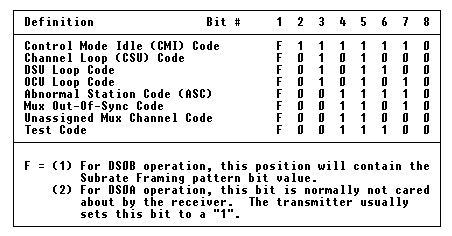
The following chart represents some of the DS0 network control codes that may be used.

DS0 Hexadecimal Numbering Conventions
It is important to observe that on a DS0, the Most Significant Bit (MSB) is transmitted first. This differs somewhat from the Hexadecimal numbering scheme that we are accustomed to in conventional data transmission. For example: If, in normal data transmission terms, a Hex “7F” was transmitted, the first bit transmitted (LSB) would be a “1”. This would be followed by six more “1”s, then the last bit (MSB) would be a “0”.
On a DS0 basis, however, this same Hexadecimal value (7F) means that the first bit transmitted would be a “0” (MSB). The eighth and last bit, the Least Significant Bit (LSB), would be a “1”. This “7F” value, by the way, is the code normally transmitted in undefined T1 DS0s.
Test Equipment
On the Line Side of DDS, it is usually necessary only to have a spare DSU on hand for testing purposes; since the cost of spare DSUs is less than that of available test equipment. On the DS0 side of DDS, specialized test equipment is needed. I prefer the classy Hewlett Packard equipment for this purpose. Often, generic DS0 data test sets can be used to figure out what is going on with a DDS channel, but the DS0 numbering conventions must be clearly understood.
Most test equipment capable of looking at an individual DS0 will usually provide only a binary readout of the bits present in the DS0, however, there are some exceptions. When using the Phoenix 5500A’s Digital Data Trap, the DS0 may be viewed in Binary, HXM, or HXL format. The HXM format should be used in this case (HXM means that the leftmost bit [the first received] of each word is the Most Significant Bit).
When using the User Patterns in the Phoenix 5500A to test a DS0, it is important to note that the User Patterns are entered in “standard” data transmission Hexadecimal format. For example: To emulate a “7F” code output from an ILP DS0, it will be necessary to define a Phoenix 5500A User Pattern consisting of “FE” words!