| RETURN | Protocol Information |
Facsimile HDLC Protocol Overview
This document discusses the ubiquitous Group 3 FAX machine, and it’s use of an HDLC protocol for FAX control purposes. Nearly all Group 3 FAX machines transmit this HDLC protocol information at a rate of 300 BPS, although 2400 BPS is an option.
Preamble
The preamble precedes all binary coded information whenever transmission begins in any new direction (e.g. at each “Line Turn-Around” time). The preamble consists of a series of flag characters for 1 Second +/- 15% (850 mS to 1.15 S), at a rate of 300 BPS.
HDLC Frame Structure
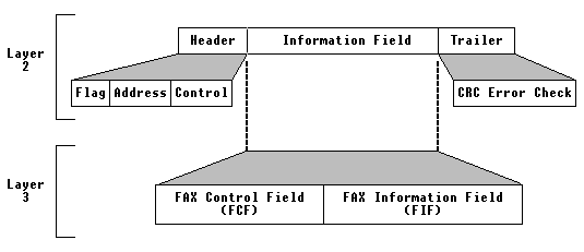
The HDLC frame contains a beginning flag, a single byte address field, a single byte control field. The control field is then followed by a variable length information field and a Frame Check Sequence (FCS) that is two bytes (16 bits) long.
- Flag
- Address
- Control
- Information Field
- Frame Check Sequence


Flag Sequence
The flag sequence is used for synchronization and is comprised of a single 8-bit (1 byte) sequence of “01111110” (hex “7E”). Continued transmission of the flag sequence may be used to signal to the distant station that that device remains on-line but is not prepared for further FAX processes.
Address Field
The address field is comprised of a single 8-bit byte, with the bit sequence of “11111111” (hex “FF”).
Control Field
The control field is again comprised of a single 8-bit byte. This byte has the bit sequence of “1100X000”. The value of X equals “0” when this is a non-final frame, while the value of X equals “1” for final frames within a procedure.
Information Field
The information field may be of variable length and is actually comprised of two distinct elements; the FAX Control Field (FCF) and the FAX Information Field (FIF).
Frame Check Sequence
The FCS is comprised of 16-bits (2 bytes) that represent a standard CCITT FCS polynomial. This field is used by the recipient to determine the accuracy of the information received.
The generator polynomial used is: X16 + X12 + X5 + 1. The ITU/CCITT CRC check (CRC-CCITT) is not the same polynomial that is used in IBM Bisync (CRC-16).


The CRC process has the advantage that the current shift register state is based upon the past history of bits. Therefore, it is very robust in picking up bursts of errors. In fact, the CRC check will detect 99.9% of all error bursts greater than 16 bits in length.
Line Error Control
The transmission of a response is permitted only when receiving a VALID command. Upon timeout (3 S +/- 15%) the transmitting station will retransmit the command.
However, an optional CRP (Command Repeat) message may be sent from the receiver requesting the retransmittal of the command. The use of the OPTIONAL CRP message can shorten the retransmission time (e.g. the Sender does not have to wait for the expiration of the 3 second timer).