| RETURN | ISDN Technology |
ISDN D-Channel Operation
OSI Model Conformance
ISDN operations conform to the general layers specified in the OSI model as indicated in the diagram below:

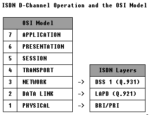
Layer 1 (Physical Services) are the actual framing and line coding used by the Basic Rate and Primary Rate ISDN lines. This layer is described in other ISDN sections.
Layer 2 (Data Link) is described herein. The D-Channel utilizes a HDLC (High-level Data Link Control) protocol called LAPD, the “Link Access Procedure D-channel”. This is somewhat analogous to the Data Link layer in X.25 communications, known as LAPB (Link Access Protocol Balanced) and Frame Relay’s equivalent: (LAPF). Operation of LAPD is detailed in ITU Recommendation Q.921.
Layer 3 (Network) is also described herein. This is known as DSS 1 (Digital Subscriber Signalling System #1) and is detailed in ITU Recommendation Q.931. This function is responsible for the actual setup and teardown of ISDN calls.

Layer 2 Description
- Flag
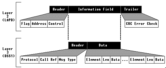
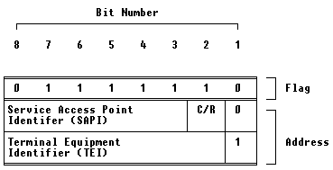
The Flag character is part of the Header information and is used to maintain synchronization between transmitter and receiver. The Flag character is a hexadecimal “7E”, or binary “01111110”. The Flag character may be appened to the end of a block (trailer) as well. In most point-to-point HDLC applications, each end will “idle flags”.
- Address
The Address is two bytes (octets) long, and consists of three fields: (1) the Service Access Point Identifier (SAPI), (2) a Command/Response (C/R) bit, and (3) the Terminal Endpoint Identifier (TEI).

- Control
The Control field may be either one or two octets (bytes) in length. The Control field indicates one of three frame formats: (1) Information format, (2) Supervisory Format, or (3) Unnumbered format. The Control field is two bytes long for the Information and Supervisory formats, and a single byte in length for the Unnumbered format. Only the Information and certain types of Unnumbered frames may have an information field associated.
The Information format contains Layer 3 data, but some information may be sent in Unnumbered Information frames or XID frames. The Unnumbered Information frame is useful because it is often used when requesting TEI assignment from the ISDN switch. The SABME (Set Asynchronous Balanced Mode Extended) is a type of Unnumbered frame that reinitializes the data link layer. The XID frame is often used to exchange parameters, such as window sizes, timer values, and frame sizes after TEI acquisition.
RR (Receiver Ready), RNR (Receiver Not Ready), and REJ (Reject) messages utilize the Supervisory frame format.
- Information
The Information field is used to carry Layer 3 Call Control (Q.931) data. In certain cases, it may carry Unnumbered Information data (TEI assignment) or XID (Connection Management/parameter negotiation) information.
- CRC Error Check
Each frame is suffixed with two octets (bytes) of a CRC code (Cyclic Redundancy Check). This is commonly called the FCS (Frame Check Sequence). The CRC is generated by the transmitting entity and compared at the receiver for errors.
Layer 2 Bit Stuffing
The Flag character is a unique bit-sequence consisting of 01111110 (hexadecimal “7E”). Within an HDLC frame, the flag character is not allowed to appear, so a “bit stuffing” algorithm is employed.
Between Flag characters, the transmitter will insert a “0”-bit after any sequence of 5 consecutive “1”s.
At the receiving end, if 6 consecutive “1”s are received, the character is interpreted to be a Flag character. If 7 or more consecutive “1”s are received, the receiver interprets this as an abort sequence and ignores the received frame. If the receiver gets five consecutive “1”s followed by a “0”, the zero is simply deleted.
TIP: This operation can be used to provide a unique “fix”. For example, if your digital facility is sensitive to consecutive zeroes (eg. AMI), its possible to run with an “inverted D-Channel”. Most of the carrier-class PRI ISDN switches have some type of support for this operation. In this manner, the T1 line will never have more the 6 consecutive “0”s on the line except in cases of aborted frames!
Layer 3 Description


- Protocol Discriminator
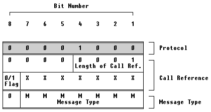
The Protocol Discriminator is part of the Layer 3 header information. It is a single byte (octet) that is usually set to a value of 00001000 (hexadecimal “08”) – meaning Q.931 Call Maintenance. It’s been observed that AT&T (now Lucent) PRI systems have also used the value, 00000011 (hexadecimal “03”) for Maintenance purposes (putting B-Channels in-service/out-of-service).
- Call Reference Value
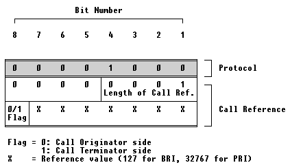
The Call Reference value consists of either two or three bytes (octets). BRI systems have a 7-bit Call Reference value (127 references) and consist of two bytes. PRI systems have a 15-bit Call Reference value (32767 references). The Call Reference value has no particular end-to-end significance. Either end can assign an arbitrary value. The Call Reference value is used to associate messages with a particulary channel connection.
It is possible to have two different calls using the same Call Reference value. This is permissible by using the Call Reference Flag bit to associate which end of the link originated the call. The following diagram depicts a BRI Call Reference field:

- Message Type
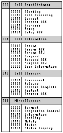
The Message Type is a single byte (octet) that indicates what type of message is being sent/received:
There are four general categories of messages that might be present: Call Establishment, Call Information, Call Clearing, and Miscellaneous. Generally, the most useful messages to understand are the Call Establishment and Call Clearing messages.
- Information Elements
Each type of message has Mandatory and Optional Information Elements associated with it. The Information Element is identified with a single byte (octet). While there are few single octet (byte) Information Elements, most have multiple octets associated with them.
When Information Elements consist of multiple octets, the byte (octet) immediately following the Information Element Identifier is used to describe how many bytes (octets) are in the Information Element. Therefore, the receiver knows where to start looking for the next Information Element in a message.
Some of the Information Elements are listed below:
- Bearer Capability (identifies transport requirements of the requested B-Channel)
- Cause (identifies reasons for disconnect or incomplete calls)
- Channel Identification (indentifies type and number of B-Channel(s) requested)
- Progress Indicator (Indicates status of outgoing call)
- Network Specific Facilities (Useful for North American PRI calls – identifies network type, Carrier ID, Carrier Service Type[WATS/SDN/ASDS,etc.])
- Calling Party Number (identifies caller)
- Calling Party Number Subaddress
- Called Party Number (destination number, type of number[unknown], numbering plan[national,etc])
- Called Party Number Subaddress

