| RETURN | ISDN Technology |
ISDN Interfaces
Overview
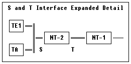
The ITU standards that define ISDN standards define specific equipment types within the ISDN network. Also, specific 2-wire and 4-wire interconnection points are defined as indicated in the following diagrams:


- The Exchange Termination (ET) and Line Termination (LT) comprise the Central Office interface, called the V-Interface.
- The U-Interface is the standard interface in the United States. It terminates the 2-wire 2B1Q-coded line from the Central Office.
- The NT-1 is a Network Termination Unit. It converts the 2-Wire 2B1Q line code into a 4-wire code used on the S and T interfaces. Most equipment used in North America WILL NOT have a S or T interface connector.
- The NT-2 is a Network Termination Unit. It is ISDN capable at both sides of the unit. A good example would be an ISDN PBX or ISDN concentrator.
- The S and T interface terms are largely interchangeable. They are both 4-wire interfaces.
- A TE1 device is an ISDN-capable Terminal Equipment.
- A TE2 device is a non-ISDN capable Terminal Equipment (e.g. standard telephone set, etc.).
- The TA is a Terminal Adapter, and is responsible for interfacing non-ISDN equipment to the ISDN line.
BRI Cabling and Pinouts
Basic Rate ISDN lines can use straight (“flat”) modular cable, if necessary. However, twisted-pair is most often used.
- ISDN U-interface
     RJ-45 Pin      Description
     ---------      -----------
        1           N/C
        2           N/C
        3           N/C
        4           U-interface
        5           U-interface
        6           N/C
        7           Optional -48 VDC Power
        8           Optional -48 VDC Return
The U-Interface is most commonly used in North American Basic Rate ISDN systems. The U-Interface is an 8-conductor, modular, RJ-45 jack. The two center pins (pins 4 and 5) are used for the 2-wire loop. The wiring of pins 4 and 5 are not polarity sensitive (e.g. 4 and 5 may be crossed).Optional -48 VDC power may be utilized on RJ-45 pins 7 and 8. This can be used to power the NT-1 and TE equipment if sufficient power is available. In most cases, power is not provided from the telephone company.
- BRI S-Interface
     RJ-45 Pin      Description
     ---------      -----------
        1           N/C
        2           N/C
        3           Receive +
        4           Transmit +
        5           Transmit -
        6           Receive -
        7           Optional -48 VDC Power
        8           Optional -48 VDC Return
The BRI S-Interface is a 4-wire interface, with separate Transmit and Receive pairs. It can operate in four modes:- Point-to-Point Mode allows one logical terminal that may be up to 1 KM from the NT-1
- Short Passive Bus Mode allows connection of up to 8 terminals in parallel on the S/T bus. The terminals can be within 100 to 200 meters from the NT-1.
- Extended Passive Bus Mode allows connection to 8 terminals at distances of up to 500 meters from the NT-1.
- Star Bus Mode allows interconnection of up to 8 terminals to a central NT-1. Each terminal can be up to 1 KM from the NT-1.
- The NT-1 unit has configurable jumpers to apply a 100-ohm termination to the S-Interface signal pairs. Usually, these jumpers will be in. Rules of termination is similar to that of the SCSI-bus: the NT-1 will have 100-ohm terminators applied, and the farthest TE1/TA device will have 100-ohm terminators.
- Optional power to the NT-1 can be applied from pins 7 and 8 of the S-Interface RJ-45 jack. This is usually not used.
- Many NT-1 units provide “phantom-power” (sealing current) between the transmit (4,5) and receive (3,6) leads. In these cases, the Transmit (4,5) leads will be negative with respect to the Receive (3,6) leads. This is often selectable in the NT-1. Whenever possible, it is recommended that this option be disabled. As a general rule-of-thumb, most PC cards, routers, and other data communications equipment do not require power from the S/T interface. ISDN telephones usually do require power from the S/T interface.
- Most NT-1 units will with a wall-mount transformer power supply to supply power to the NT-1.