| RETURN | ISDN Technology |
The PRI U-Interface
Primary Rate ISDN systems always interconnect at the U-Interface. North American systems transmit a full-duplex signal of 1.544 MBPS. This includes 23 B-Channels (1472 KBPS), 1 B-Channel (64 KBPS), and a framing/synchronization pattern (8 KBPS).
International ISDN systems transmit a full-duplex signal of 2.048 MBPS. This includes 30 B-Channels (1920 KBPS), 1 B-Channel (64 KBPS), and a framing/synchronization pattern (64 KBPS).
North American T1 PRI Line Coding
In North American Primary Rate ISDN systems, transmission of T1 signals normally occurs over Twisted-Pair cable using one of two types of line coding – AMI or B8ZS. B8ZS is more commonly used in this application. At the DSX-1 (Digital Cross-Connect Level 1) interconnection, a typical pulse amplitude of +/- 3V Peak-Base is transmitted. A termination impedance of 100 ohms is used. Line coding is defined in ITU Recommendation G.703 and a variety of US standards.
- AMI Line Coding
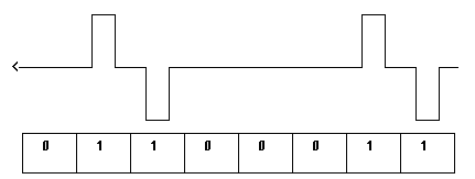
Alternate Mark Inversion (AMI) is a common line coding scheme used in North American T1 (1.544 MBPS) systems. With AMI, a positive or negative pulse is generated with each Mark (1). The pulse polarity depends upon the polarity of the last preceding pulse.
When digital line codes are utilized, it is important to prevent a build-up of DC voltage. AMI easily handles this problem.
When a Space (0) is transmitted, there are no pulses generated. Repeaters usually require pulse transitions to recover and regenerate timing on the line, so long strings of zeroes must be avoided. As a general rule to ensure compatibility, no more than 15 consecutive zeroes should be transmitted.


- B8ZS Line Coding
Bipolar 8 Zero Substitution (B8ZS) is a newer line encoding scheme used on most new North American T1 lines. B8ZS offers “clear channel” capabilities. Most ESF lines or T1 PRI lines ordered today will utilize B8ZS coding.
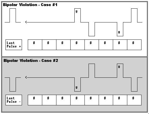
AMI’s problem with loss of timing recovery with consecutive zeroes is solved with B8ZS coding. One of two special bipolar violation code is substituted for strings of 8 zeros. Intentional bipolar violations are caused in bit positions 4 and 7 of the data stream. With B8ZS encoding, no more than 7 consecutive zero voltage states will be transmitted on the line.
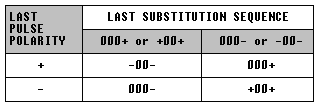
The bipolar violation codes cause two Bipolar Violations of opposite polarity in the bit stream, thus preventing excessive DC voltage levels. The bipolar violation code used depends upon the polarity of the last preceding pulse:


International E1 PRI Line Coding
International E1 systems utilize HDB3 (High Density Bipolar 3) line coding. There are two kinds of transmission media used to transmit E1 signals – Coaxial cable and Twisted-Pair cable.
With Coaxial transmission, a termination impedance of 75 ohms is used. The transmission is unbalanced, and the nominal pulse amplitude is 2.37 V Peak-Base. With Twisted-Pair cable, the transmission is balanced and terminated with a 120 ohm impedance. The nominal pulse amplitude with Twisted-Pair transmission is 3 V Peak-Base. Both transmission schemes can accomodate loss up to 6 dB.
Both transmission schemes are defined in ITU Recommendaton G.703. When interfacing to E1 systems, it is important to identify the type of transmission being used (balanced/unbalanced) and the type of connectors and cables required for the equipment interconnection.
- HDB3 Line Coding
This is again similar to AMI and B8ZS coding, except that strings of 4 zeroes are replaced with one of four bipolar violation codes. HDB3 ensures that no more than 3 consecutive zero voltage states will be transmitted on the line.
The first violation transmitted is a single pulse in bit position 4. Subsequent violations always occur in bit position 4, depending upon the previous Violation code and the last preceding pulse polarity. Refer to the state table below:


A string of 8 consecutive zero bits will be encoded to a pulse stream as indicated in this diagram:


North American T1 Framing
A T1 frame consists of 193 bits. 192 bits contain a byte of data for each of the 23 B-Channels and a byte of data from the D-Channel (8×24=192). A single bit is prefixed to the data for framing/synchronization purposes.
A D4-framed system combines 12 frames (193 bits/frame) into a Superframe.
An ESF-framed system combines 24 frames (193 bits/frame) into a Extended Superframe.
Go here for more information about North American T1 framing.
International E1 Framing
An E1 frame consists of 256 bits. 240 bits are used to transport a byte of data for each of the 30 B-Channels. 8 bits are used to transport a byte of D-Channel data and 8 bits are used for framing/synchronization purposes.
16 frames are combined for form a Multiframe.
Go here for more information about CCITT (ITU-T) E1 framing.